Category: Maritime Quick Answers

Clear, formula-first answers for maritime examination candidates and working seafarers.

  • Chief Mate Stability Formulas: Quick Revision and Worked Examples

    Back to Maritime Quick Answers
    Preparing for Phase 1 Cargo?View course

    This Chief Mate stability formula guide brings together the calculations used to find KG, GM, free-surface correction, GZ, list and change of trim. Each section gives the formula, explains when to use it and shows a short worked example.

    Quick answer: which stability formula do I need?

    • To find initial stability: GM = KM − KG.
    • After loading or discharging: calculate the final KG from total vertical moments and final displacement.
    • After shifting a weight vertically: calculate the rise or fall of G, then update KG and GM.
    • For slack tanks: divide total free surface moment by displacement and subtract the correction from GM.
    • For a righting lever at a stated angle: GZ = KN − KG × sin θ.
    • For a small angle of list: divide the transverse heeling moment by displacement × corrected GM to find tan θ.
    • For change of trim: divide the trimming moment by MCTC.

    Use the units beside each formula. Displacement and weights are in tonnes; distances are in metres unless stated otherwise. All worked examples use original training figures. They are separate examples, not successive stages of one ship’s loading condition.

    1. KG, KM and GM

    Use this to find the ship’s initial transverse metacentric height. Read KM for the relevant displacement and trim from the hydrostatic data, and use KG for the same loading condition.

    GM = KM − KG

    KG = KM − GM

    KM = KB + BM

    TermMeaning
    KKeel datum used for the vertical measurements.
    KGHeight of the ship’s centre of gravity, G, above K.
    KBHeight of the centre of buoyancy, B, above K.
    BMTransverse metacentric radius, from B to the initial metacentre M.
    KMHeight of the initial transverse metacentre above K.
    GMInitial transverse metacentric height, from G to M.

    Short example

    KM = 7.20 m and KG = 6.30 m.

    GM = 7.20 − 6.30 = 0.90 m

    If 6.30 m is the solid KG, this is the GM before free-surface correction.

    A positive corrected GM describes initial stability. It does not, by itself, confirm adequate stability at larger angles or compliance with every applicable criterion.

    2. Final KG after loading and discharging

    Use moments about K. Loading adds weight and its vertical moment; discharging removes both.

    Vertical moment = Weight × Height of its centre of gravity above K

    Final displacement = Initial displacement + Weights loaded − Weights discharged

    Final KG = Final total vertical momentFinal displacement

    The starting vertical moment is initial displacement × initial solid KG. Add each loaded weight × its height above K, and subtract each discharged weight × its height above K.

    Short example: load one weight and discharge another

    A ship initially displaces 10,000 t with KG 6.00 m. She loads 1,000 t at 4.00 m above K and discharges 500 t from 8.00 m above K.

    ItemWeight (t)Height above K (m)Moment (t·m)
    Initial ship10,0006.0060,000
    Load cargo+1,0004.00+4,000
    Discharge cargo−5008.00−4,000
    Final total10,500—60,000

    Final KG = 60,00010,500 = 5.714 m

    At the final displacement, the supplied hydrostatic KM is 7.000 m.

    Final GM = 7.000 − 5.714 = 1.286 m

    No free-surface correction is included in this example.

    Check the direction: loading below the original G and removing weight above it both lower KG in this example.

    Use the final displacement in the denominator and obtain the final KM. Loading and discharging may change KM as well as KG. Tank liquid weights belong in the weight-and-moment table; their free-surface effect is an additional correction.

    Reference for the moment-table method: MCA example stability booklet, KG and condition table.

    3. Rise or fall of G when a weight is shifted vertically

    Use this when the weight is already on board. Moving it to another height changes the position of G without changing displacement.

    Rise or fall of G = Weight shifted × Vertical distance movedShip’s displacement

    Weight moved up: New KG = Old KG + Rise of G

    Weight moved down: New KG = Old KG − Fall of G

    Short example: moving cargo upwards

    A 200 t weight is raised 5.00 m on a ship displacing 10,000 t. Initial KG = 6.00 m; KM remains 7.00 m.

    Rise of G = 200 × 5.0010,000 = 0.100 m

    New KG = 6.00 + 0.10 = 6.10 m.

    New GM = 7.00 − 6.10 = 0.90 m.

    Raising the weight reduces GM from 1.00 m to 0.90 m.

    The distance is the change in the weight’s height, not its final height above K. This example assumes unchanged free-surface effects.

    4. Free-surface correction and corrected GM

    Use this when slack tanks contribute a free surface moment. Add the applicable tank moments before dividing by displacement.

    Free surface correction = Total free surface momentShip’s displacement

    Corrected GM = Uncorrected GM − Free surface correction

    Fluid KG = Solid KG + Free surface correction

    FSM means free surface moment, in t·m. FSC means free surface correction, in metres. Use the tank moments and density adjustment specified in the question or tank tables.

    Short example: two slack tanks

    Displacement = 12,000 t; tank moments = 800 t·m and 400 t·m; uncorrected GM = 0.90 m.

    FSC = 800 + 40012,000 = 0.100 m

    Corrected GM = 0.90 − 0.10 = 0.80 m

    Apply FSC once. If GM was calculated as KM − fluid KG, it is already corrected. Do not subtract FSC again. If a given FSM already includes liquid density, do not multiply it by density again.

    Read the full Free-Surface Effect explanation and tank calculation →

    5. GZ, KN and righting moment

    Use KN to calculate GZ at a specified angle of heel. Obtain KN from the correct displacement and trim data, interpolating when necessary. For a ship with G on the centreline:

    GZ = KN − KG × sin θ

    Righting moment = Displacement × GZ

    GZ is the righting lever in metres; θ is the angle of heel. Use the KG and free-surface method specified in the question. In the conventional fluid-KG method, use fluid KG = solid KG + FSC.

    Short example: GZ at 30°

    At the required displacement, KN at 30° = 3.50 m. The applicable KG, already corrected as required, is 6.00 m. Displacement = 12,000 t.

    GZ = 3.50 − 6.00 × sin 30°

    = 3.50 − 3.00 = 0.50 m

    Righting moment = 12,000 × 0.50 = 6,000 t·m

    The moment is written in the usual exam convention of tonne-metres. If a question asks for kN·m, convert the displacement weight to kilonewtons before multiplying by GZ.

    What about GZ = GM × sin θ?

    At small angles: GZ ≈ GM × sin θ

    This is an initial-stability approximation, with G on the centreline and the metacentre treated as fixed. For example, corrected GM 0.80 m at 5° gives GZ ≈ 0.80 × sin 5° = 0.070 m. Use the KN data or GZ curve for larger angles.

    Use degree mode when θ is in degrees. Do not subtract FSC from GZ as a plain distance, and do not apply a further free-surface correction when the supplied KG or GZ is already corrected.

    Read the full GZ and KN calculation, interpolation and curve example →

    Reference for the KN relationship and fluid KG: MCA example stability booklet, KN tables.

    6. Angle of list after a transverse weight shift

    Use this for a small equilibrium list caused by moving a weight across an initially upright ship. The weight remains on board and moves horizontally, so displacement and KG are unchanged.

    Heeling moment = Weight shifted × Transverse distance moved

    tan θ = Weight shifted × Transverse distance movedDisplacement × Corrected GM

    Find θ using the inverse tangent, tan⁻¹.

    Short example: shifting cargo to starboard

    Displacement = 10,000 t; corrected GM = 0.80 m. A 100 t weight is moved 4.00 m to starboard at the same height.

    tan θ = 100 × 4.0010,000 × 0.80 = 0.050

    θ = tan⁻¹(0.050) = 2.86° to starboard

    0.050 is the tangent, not the angle. If the weight also moves vertically, calculate the new GM first. If a weight is loaded or discharged off-centre, calculate the final displacement, final corrected GM and net transverse heeling moment for that condition.

    This formula assumes positive corrected GM and a small angle. An angle of loll caused by negative initial GM is a different problem; do not use this list calculation to diagnose or correct it.

    The same moment–tangent relationship underlies the inclining experiment: NAVSEA, Weights and Stability, section 096-2.1.2.1.

    7. Change of trim when a weight is shifted longitudinally

    Use MCTC for a fore-and-aft weight movement. MCTC is the moment to change trim by one centimetre, in t·m/cm.

    Trimming moment = Weight shifted × Longitudinal distance moved

    Change of trim (cm) = Trimming momentMCTC

    Shifting a weight aft produces a change of trim by stern; shifting it forward produces a change by head. Use the distance moved for an onboard shift.

    Short example: shifting a weight aft

    A 200 t weight is shifted 20.00 m aft. MCTC = 200 t·m/cm.

    Trimming moment = 200 × 20.00 = 4,000 t·m

    Change of trim = 4,000200 = 20.00 cm by stern

    That is a 0.200 m change of trim. It is not automatically the final trim.

    How is the change divided between forward and aft drafts?

    For the small-change calculation, the ship trims about LCF. On this page, LCF is measured forward from AP.

    Aft draft change due to trim = Change of trim × LCF from APLBP

    Forward draft change due to trim = Change of trim × (LBP − LCF from AP)LBP

    These give the magnitudes. For a change by stern, add at AP and subtract at FP. For a change by head, reverse those signs.

    Continue the example: calculate final drafts

    LBP = 150.00 m; LCF = 70.00 m forward of AP. Initial drafts at the perpendiculars are F 6.000 m and A 6.200 m. Assume MCTC and LCF remain constant over this small change.

    • Aft increase = 20.00 × 70.00 ÷ 150.00 = 9.333 cm = 0.09333 m.
    • Forward decrease = 20.00 × 80.00 ÷ 150.00 = 10.667 cm = 0.10667 m.
    • Final F = 6.000 − 0.10667 = 5.893 m.
    • Final A = 6.200 + 0.09333 = 6.293 m.
    Final trim = 6.293 − 5.893 = 0.400 m by stern.

    Check: initial trim 0.200 m + change by stern 0.200 m = 0.400 m by stern.

    Do not divide the trim change equally unless LCF is amidships. Keep both the change of trim and the resulting draft changes in the same unit, then convert centimetres to metres before updating drafts in metres.

    If the weight is loaded or discharged instead

    There is also a change in displacement. For a small weight change, calculate the parallel sinkage or rise using TPC, as well as the trim effect about LCF:

    Parallel sinkage or rise (cm) = Weight loaded or dischargedTPC

    TPC is tonnes per centimetre immersion. Use the weight’s distance from LCF to calculate its trimming moment when loading or discharging. For larger changes, follow the question’s hydrostatic procedure instead of assuming TPC, MCTC and LCF stay constant.

    A useful order for a combined stability question

    1. Find final displacement after all loading and discharging.
    2. Find final solid KG from the weight-and-moment table, including any vertical shifts.
    3. Obtain final KM from the hydrostatic data for that condition.
    4. Calculate FSC from the applicable slack-tank moments.
    5. Find corrected GM or fluid KG, applying FSC once.
    6. Calculate the quantity asked for: GZ, righting moment, list, or trim and final drafts.

    Common Chief Mate exam mistakes

    • Using initial displacement after loading or discharging. Recalculate the final total.
    • Using a weight’s height instead of its distance moved. Height above K belongs in a vertical-moment table; distance moved belongs in a shifting calculation.
    • Keeping KM unchanged without checking. Obtain the hydrostatic value for the new condition.
    • Correcting twice for free surface. Distinguish solid KG, fluid KG and corrected GM.
    • Using GM × sin θ at a large angle. Use the KN values or GZ curve supplied.
    • Writing tan θ as the answer in degrees. Take the inverse tangent.
    • Confusing list with loll. The small-angle list formula assumes positive corrected GM.
    • Treating change of trim as final trim. Combine it with the initial trim, keeping the direction clear.
    • Mixing centimetres and metres. MCTC and TPC normally give changes in centimetres.
    • Rounding at every step. Keep calculator precision and round the final answer to the question’s requirement.

    Quick oral-exam answers

    Does loading a weight always reduce GM?

    No. Its effect depends on the position of the added weight and the change in KM. Calculate the new KG and use the new hydrostatic KM.

    Does shifting a weight change displacement?

    No, provided it remains on board and no other weight is added or removed. Its movement changes the position of G.

    Are GM and GZ the same?

    No. GM describes initial stability near the upright condition. GZ is the righting lever at a particular angle of heel.

    Does a positive GM mean the loading condition is acceptable?

    It is one check. The relevant GZ curve, stability limits, downflooding and other required criteria must also be considered using the ship’s approved information.

    For the role of approved loading instructions and stability limits, see the US Coast Guard guidance on trim and stability booklets. This page is a revision guide to core calculations, not a complete stability syllabus.

    Also preparing for Chief Mate Cargo?

    Build your numerical practice with the WayToMasters Hindship course: 9 complete problems, written solutions, video explanations, and formulas and common mistakes material.

    Get 180 days of access for focused Phase 1 Cargo practice.

    View the Hindship Cargo course
  • COLREG Rules 1–19: Oral Exam Questions and Answers

    Back to Maritime Quick Answers
    Preparing for Phase 1 Cargo?View course

    Prepare for Chief Mate and deck officer oral examinations with short answers to International COLREG Rules 1–19. Start with the rule, explain the duty, then describe how you would assess and monitor the situation.

    Quick answer: how should I approach a COLREG oral question?

    • Establish visibility and visual contact. Are the vessels in sight of one another? Are you in or near restricted visibility?
    • Identify the vessels and setting. Consider vessel status, a narrow channel, a traffic separation scheme and any overtaking situation.
    • Assess collision risk. Use all appropriate available means; one bearing or an AIS label is not enough.
    • State the applicable duty and action. Explain who must do what, and any qualifications.
    • Check the result. Continue observing until the other vessel is finally past and clear.

    These are practice questions and model answers, written for revision. Read them alongside the full International Rules; the short answers do not reproduce every provision.

    Which COLREG rules apply?

    RulesApplication
    1–3General application, responsibility and definitions.
    4–10Conduct of vessels in any condition of visibility.
    11–18Conduct of vessels in sight of one another. This means visual observation.
    19Vessels not in sight of one another when navigating in or near an area of restricted visibility. Rules 4–10 still apply.

    Oral trap: detecting a vessel by radar or AIS does not make the vessels “in sight.” Darkness alone is not restricted visibility.

    Reference: official navigation rules, Rules 3, 4, 11 and 19. The linked publication includes both International and US Inland text; use the International provisions for this guide.

    Rules 1–3: general rules and definitions

    Rule 1 — Application

    Where do the International COLREGs apply?
    To all vessels on the high seas and in connected waters navigable by seagoing vessels.

    Can there be local rules?
    Yes. Appropriate authorities may make special rules for places such as harbours, roadsteads, rivers and inland waterways. Those rules must conform as closely as possible to COLREGs.

    Follow-up: warships and special-purpose vessels are not generally exempt. Rule 1 permits specified additional signals for warships, convoys and fishing fleets. Where a special-purpose vessel cannot fully meet specified light, shape or sound-signal requirements, government-approved alternatives must achieve the closest possible compliance.

    Rule 2 — Responsibility

    Does following one rule automatically remove responsibility?
    No. The vessel, owner, master and crew remain responsible for neglect of the Rules and of precautions required by ordinary seamanship or the circumstances.

    When may departure from the Rules be necessary?
    When special circumstances, including the limitations of the vessels involved, make departure necessary to avoid immediate danger. Rule 2 is not permission to depart merely for convenience.

    Follow-up: calling the master does not suspend the officer of the watch’s duty to take necessary action.

    Rule 3 — General definitions

    Which definitions must I distinguish clearly?

    TermOral answer
    Power-driven vesselA vessel propelled by machinery.
    Sailing vesselA vessel under sail, with any fitted propulsion machinery not being used.
    Engaged in fishingFishing with apparatus that restricts manoeuvrability. Trolling lines or other gear that does not restrict manoeuvrability do not qualify.
    NUCNot under command: an exceptional circumstance prevents the vessel from manoeuvring as the Rules require, so she cannot keep out of another vessel’s way.
    RAMRestricted in ability to manoeuvre: the nature of her work restricts manoeuvring as required by the Rules, so she cannot keep out of another vessel’s way.
    CBDConstrained by draught: a power-driven vessel severely restricted in deviating from her course because of draught in relation to available depth and width of navigable water.
    UnderwayNeither at anchor, nor made fast to the shore, nor aground.
    In sightOne vessel can be observed visually from the other.
    Restricted visibilityVisibility restricted by fog, mist, falling snow, heavy rainstorms, sandstorms or similar causes.

    Is underway the same as making way?
    No. Making way refers to movement through the water. A vessel can be underway without making way. Stopping engines does not automatically make a vessel NUC.

    Give examples of RAM work.
    Servicing navigation marks or submarine cables/pipelines; dredging, surveying or underwater work; replenishment or transfers while underway; launching or recovering aircraft; mineclearance; and towing that severely restricts the towing vessel and tow in deviating from their course. The list is not exhaustive.

    Other definitions to revise: “vessel” includes non-displacement craft, WIG craft and seaplanes used or capable of use as transport on water. Length means length overall; breadth means greatest breadth. A seaplane is an aircraft designed to manoeuvre on water; WIG craft use surface-effect action close to the surface.

    Source: International Rules 1–3.

    Rules 4–10: conduct in any visibility

    Rule 4 — Application

    Do Rules 5–10 stop applying in fog?
    No. Rule 4 makes this section applicable in any condition of visibility. Look-out, safe speed, collision-risk assessment and the other duties continue when Rule 19 applies.

    Rule 5 — Look-out

    What is a proper look-out?
    Every vessel must maintain one at all times, using sight, hearing and all available means appropriate to the conditions, to fully assess the situation and collision risk.

    Follow-up: radar and AIS support the look-out; they do not replace looking and listening. A vessel at anchor is also subject to Rule 5.

    Rule 6 — Safe speed

    What makes a speed safe?
    It must allow proper and effective collision-avoidance action and stopping within a distance appropriate to the conditions.

    What factors apply to all vessels?

    • Visibility.
    • Traffic density, including fishing vessels and other concentrations.
    • Manoeuvrability, especially stopping distance and turning ability.
    • At night, background lighting and backscatter from the vessel’s own lights.
    • Wind, sea, current and nearby navigational hazards.
    • Draught relative to available water depth.

    What additional factors apply with operational radar?

    • The radar’s characteristics, efficiency and limitations.
    • Constraints caused by the selected range scale.
    • Effects of sea state, weather and interference.
    • Possible failure to detect small vessels, ice or floating objects at adequate range.
    • The number, position and movement of detected vessels.
    • The more exact assessment of visibility possible from radar ranges of nearby vessels or objects.

    Oral trap: the rule sets no universal speed in knots. Good visibility or working radar does not, by itself, justify full speed.

    Rule 7 — Risk of collision

    How do you determine collision risk?
    Use all appropriate available means. If in doubt, assume the risk exists. Use fitted, operational radar properly, including long-range scanning and plotting or equivalent systematic observation.

    Does an unchanging bearing prove risk?
    An approaching vessel whose compass bearing does not appreciably change must be treated as a collision risk. An appreciable bearing change can still leave risk, especially with a very large vessel, a tow or a vessel at close range.

    Follow-up: do not reach conclusions from scanty information. A single radar observation, an unverified AIS prediction or a fixed “safe CPA” number is not a complete assessment.

    Rule 8 — Action to avoid collision

    What should effective action look like?
    It should comply with the steering and sailing rules and, where circumstances allow, be positive, made in ample time and consistent with good seamanship. Course or speed changes should be readily apparent; avoid a succession of small alterations.

    Allow safe passing distance and check effectiveness until the other vessel is finally past and clear. Course alteration alone may work if there is sufficient sea room and it creates no other close-quarters situation. If necessary, reduce speed, stop or reverse propulsion.

    Does “not impede” mean the same as “keep out of the way”?
    No. A not-impede duty requires early action, when needed, to leave sufficient sea room for safe passage. If collision risk develops, that duty continues and the applicable steering and sailing rules must also be considered.

    Follow-up: the vessel whose passage must not be impeded still has collision-avoidance obligations. She does not gain permission to stand into danger.

    Rule 9 — Narrow channels

    Where should a vessel navigate along a narrow channel?
    As near the starboard outer limit as is safe and practicable.

    • Under 20 m or sailing: must not impede a vessel that can safely navigate only within the channel or fairway.
    • Engaged in fishing: must not impede any other vessel navigating within it.
    • Crossing: must not impede a vessel that can safely navigate only within it.

    What if an overtaken vessel must help make passing safe?
    For vessels in sight, use the intention and agreement signals in Rule 34(c); the overtaken vessel, if agreeing, takes steps to permit safe passing. The overtaking vessel remains responsible under Rule 13.

    Follow-up: approach an obscured bend with particular alertness and caution and sound the Rule 34(e) signal. Avoid anchoring in a narrow channel when circumstances allow.

    Rule 10 — Traffic separation schemes

    Does using a traffic lane give automatic priority?
    No. Rule 10 applies to IMO-adopted schemes and does not remove duties under other rules.

    • Proceed in the lane’s general traffic-flow direction and keep clear of separation lines or zones as far as practicable.
    • Normally join or leave at the lane’s end. When joining or leaving from the side, use as small an angle to traffic flow as practicable.
    • Avoid crossing lanes where practicable. If obliged to cross, use a heading as close as practicable to a right angle to traffic flow.
    • Use particular caution near terminations. Avoid anchoring in the scheme or near its ends as far as practicable; non-users should keep as far clear as practicable.

    Who may use an inshore traffic zone?
    Vessels under 20 m, sailing vessels and vessels engaged in fishing may use it. Other vessels should not use it when they can safely use the adjacent lane, but may do so for destinations within the zone, including ports and pilot stations, or to avoid immediate danger.

    Can vessels enter the separation zone?
    A vessel not crossing, joining or leaving a lane should normally stay out, except in an emergency to avoid immediate danger or to fish within the separation zone.

    What are the not-impede duties?
    Fishing vessels must not impede any vessel following a lane. Sailing vessels and vessels under 20 m must not impede a power-driven vessel’s safe passage along a lane.

    Follow-up: the right-angle requirement concerns heading, not course over ground. Specific RAM exemptions for maintaining navigation safety or working on submarine cables within a scheme extend only as far as necessary for the operation.

    Source: International Rules 4–10. Rules 34 and 35 contain the detailed sound-signal requirements and should be revised alongside this page.

    Rules 11–18: vessels in sight of one another

    Rule 11 — Application

    When do Rules 12–18 apply?
    When vessels are in sight of one another. A radar target alone is not visual contact. If vessels are not in sight while navigating in or near restricted visibility, assess the encounter under Rule 19, together with Rules 4–10.

    Rule 12 — Sailing vessels

    Two sailing vessels approach with collision risk. Who keeps out of the way?

    • Wind on different sides: the vessel with wind on her port side.
    • Wind on the same side: the windward vessel keeps out of the leeward vessel’s way.
    • Port-side wind and uncertain: if a vessel sees another to windward and cannot determine which side the other has the wind on, she keeps out of the way.

    Follow-up: windward is the side opposite the mainsail; for a square-rigged vessel, use the largest fore-and-aft sail. Check Rule 13 first if one vessel is overtaking. A vessel using propulsion machinery is not a sailing vessel under Rule 3.

    Rule 13 — Overtaking

    How do you recognise overtaking?
    You are coming up from more than 22.5° abaft the other vessel’s beam: at night, a position from which you would see her sternlight but neither sidelight.

    Who keeps out of the way?
    Any vessel overtaking another. This obligation applies notwithstanding the other rules in Sections I and II. If in doubt about being the overtaking vessel, assume you are.

    Follow-up: your duty continues until finally past and clear. A later bearing change does not turn you into a crossing vessel or relieve the duty. A sailing vessel overtaking a power-driven vessel must keep out of the way.

    Rule 14 — Head-on situation

    What is required in a head-on situation?
    When two power-driven vessels meet on reciprocal or nearly reciprocal courses with collision risk, each alters to starboard so they pass port side to port side.

    How is it recognised?
    The other vessel is ahead or nearly ahead. At night, the masthead lights appear in or nearly in line and/or both sidelights are visible; by day, the corresponding aspect is seen. If in doubt, assume the situation exists.

    Oral trap: Rule 14 is a rule for vessels in sight. A radar-only target ahead in fog must be assessed under Rule 19.

    Rule 15 — Crossing situation

    Two power-driven vessels are crossing with collision risk. Who gives way?
    The vessel with the other on her starboard side keeps out of the way and, if circumstances allow, avoids crossing ahead.

    Follow-up: establish that this is a crossing encounter between two power-driven vessels in sight, and check other applicable obligations. One sighting on the starboard bow is not enough to prescribe a helm order without assessing risk, sea room and other traffic.

    Rule 16 — Action by the give-way vessel

    How should the give-way vessel act?
    As far as possible, take early and substantial action to keep well clear. Choose an effective manoeuvre consistent with the applicable rules, then monitor its result.

    Follow-up: a series of small course changes may be difficult for the other vessel to recognise and conflicts with the guidance in Rule 8.

    Rule 17 — Action by the stand-on vessel

    Must the stand-on vessel always maintain course and speed?
    No. Explain the changing duties in three stages:

    StageStand-on duty
    Initially — 17(a)(i)Maintain course and speed.
    May act — 17(a)(ii)May take avoiding action by her own manoeuvre alone as soon as it becomes apparent that the give-way vessel is not taking appropriate action.
    Must act — 17(b)When so close that the give-way vessel’s action alone cannot avoid collision, take the action that will best help avoid it.

    Can the stand-on vessel alter to port?
    In a crossing situation between power-driven vessels, a stand-on vessel acting under 17(a)(ii) must, if circumstances allow, avoid altering to port for a vessel on her own port side.

    Oral trap: this is a qualified provision for that particular situation, not a universal “never turn to port” rule. Action by the stand-on vessel does not remove the give-way vessel’s duty.

    Rule 18 — Responsibilities between vessels

    How do you explain the responsibilities?
    Start with the qualification: except where Rules 9, 10 and 13 otherwise require.

    VesselMust keep out of the way of
    Power-driven, underwayNUC, RAM, vessels engaged in fishing and sailing vessels.
    Sailing, underwayNUC, RAM and vessels engaged in fishing.
    Fishing, underwayNUC and RAM, so far as possible.

    Where does a vessel constrained by draught fit?
    Every vessel except NUC or RAM must, if circumstances allow, avoid impeding the safe passage of a CBD vessel exhibiting Rule 28 signals. The CBD vessel must navigate with particular caution. This is not an unconditional extra rung in a priority list.

    What about seaplanes and WIG craft?
    A seaplane on the water should generally stay well clear and avoid impeding vessels; where collision risk exists, it follows Part B. A WIG craft taking off, landing or flying near the surface keeps well clear of other vessels and avoids impeding them. On the water surface, it follows the rules for power-driven vessels.

    Follow-up: a pilot vessel has no special Rule 18 priority merely because it is on pilotage duty. A tug is not automatically RAM; the nature and restriction of the towing operation matter.

    Source: International Rules 11–18.

    Rule 19 — Restricted visibility

    When does Rule 19 apply?
    To vessels not in sight of one another when navigating in or near an area of restricted visibility.

    What are the immediate requirements?
    Proceed at a safe speed adapted to the conditions. A power-driven vessel must have her engines ready for immediate manoeuvre. Apply Rules 4–10 with proper regard to the restricted visibility.

    What if another vessel is detected by radar alone?
    Determine whether a close-quarters situation is developing or collision risk exists. If so, take avoiding action in ample time.

    If avoiding action is a course alteration, so far as possible avoid:
    Target positionCourse alteration to avoid
    Forward of the beamAn alteration to port, except for a vessel being overtaken.
    Abeam or abaft the beamAn alteration towards the vessel.

    What if you hear a fog signal apparently forward of the beam?
    Unless you have determined that collision risk does not exist, reduce speed to the minimum at which you can keep course. If necessary, take all way off and navigate with extreme caution until the danger is over.

    The same requirement applies when you cannot avoid a close-quarters situation with another vessel forward of the beam.

    Oral trap: Rule 19 does not assign a stand-on/give-way pair as the in-sight crossing rule does. Both vessels must assess and act as required. Other applicable duties, including narrow-channel and TSS not-impede obligations, continue.

    References: International Rule 19 and MCA guidance on navigation in restricted visibility.

    Oral practice: say your answer, then check

    These original practice situations test the distinctions above. State your assumptions; the examiner may change the visibility, vessel status or sea room.

    1. A sailing yacht is overtaking your power-driven vessel. Who keeps clear? Reveal answer

    The yacht keeps out of the way under Rule 13. The usual power-driven/sailing relationship does not displace the overtaking duty. Confirm that the vessels are in sight and the encounter meets the overtaking definition.

    2. Your engines are stopped while drifting. Are you NUC? Reveal answer

    Not automatically. You are underway if not anchored, made fast to shore or aground. NUC requires an exceptional circumstance that prevents manoeuvring as the Rules require. Describe any actual failure and its effect; stopped engines alone do not establish NUC.

    3. In a power-driven crossing encounter, the vessel on your port side is not giving way. What changes? Reveal answer

    Explain Rule 17’s stages: initially maintain course and speed; you may act when its failure to take appropriate action becomes apparent; you must act when its action alone can no longer avoid collision. Apply the qualified restriction on a port alteration under 17(a)(ii). Monitor continuously rather than waiting for a fixed distance.

    4. In fog, a radar-only target on your starboard bow has a steady bearing and decreasing range. Are you the give-way vessel under Rule 15? Reveal answer

    No. With the vessels not in sight in restricted visibility, use Rule 19 and Rules 4–10. Assess the developing encounter systematically and take avoiding action in ample time. If altering course, avoid port for a target forward of the beam so far as possible, except when overtaking it. Select action that also accounts for other traffic and sea room.

    5. A fog signal is heard ahead, but radar shows no target. Can you maintain speed? Reveal answer

    Radar non-detection does not establish absence of risk. Unless collision risk has been ruled out, Rule 19(e) requires reduction to minimum course-keeping speed, taking all way off if necessary, and extreme caution until the danger is over. Maintain the proper look-out and investigate the signal.

    6. Current is setting you along a traffic lane while you cross it. Must your track be 90° to the lane? Reveal answer

    Rule 10 specifies a heading as nearly as practicable at right angles to traffic flow, not a ground track of exactly 90°. First consider whether crossing is necessary, then assess traffic and other applicable rules.

    7. A small sailing vessel wants to cross ahead of a ship confined to a narrow channel. Does sail give priority? Reveal answer

    No. Rule 9 requires the sailing vessel not to impede the ship that can safely navigate only within the channel; the crossing provision also applies. Take early action to leave sufficient sea room. If collision risk nevertheless develops, both vessels must fulfil the applicable collision-avoidance duties.

    8. Another vessel suggests a different passing arrangement on VHF. Is agreement enough? Reveal answer

    No. Positively identifying the caller can be difficult, and misunderstandings or delayed action can create danger. Communication does not replace COLREG compliance. Assess the encounter, act under the applicable rules and use the required signals. Treat AIS as supporting information rather than the sole basis for avoidance.

    Communication reference: MCA MGN 324 Amendment 2: VHF and AIS use.

    A simple oral revision routine

    1. Name the rule and when it applies. Say whether visual contact, restricted visibility or a particular vessel type is required.
    2. Give the main duty in one or two sentences. Then add the important qualification.
    3. Answer one changed situation. For example: what if the other vessel is overtaking, or disappears into fog?
    4. Finish with assessment and monitoring. Explain how you will check that the action is working.

    Revise the exact statutory wording alongside these explanations, especially the differences between shall, may, if circumstances admit and so far as possible. Continue with lights, shapes and sound signals in Rules 20–37 for broader oral preparation.

    Official reading: IMO overview of the COLREG Convention and full navigation rules — read the International provisions.

    Also preparing for Chief Mate Cargo?

    Build your numerical practice with the WayToMasters Hindship course: 9 complete problems, written solutions, video explanations, and formulas and common mistakes material.

    Get 180 days of access for focused Phase 1 Cargo practice.

    View the Hindship Cargo course
  • Grain Stability Calculation: Formulas and Worked Example

    Back to Maritime Quick Answers
    Preparing for Phase 1 Cargo?View course

    A grain stability calculation checks whether a ship has enough stability to withstand the assumed shift of bulk grain. This Chief Mate guide follows the calculation from hold heeling moments to corrected GM, angle of heel and residual area.

    Quick answer: how do you calculate grain stability?

    • Calculate displacement and corrected GM for the loading condition.
    • Find each hold’s volumetric heeling moment (VHM) from the appropriate grain tables.
    • Divide VHM by stowage factor and apply any required grain-shift correction once.
    • Add the hold moments to obtain the ship’s total grain heeling moment.
    • Check the applicable limits using approved maximum allowable heeling moment tables or the full stability-curve method.

    The examples use invented training data. For a shipboard calculation, use the vessel’s approved grain loading manual, applicable loading conditions and instructions.

    The three grain stability criteria

    For the standard International Grain Code A 7.1 assessment:

    CheckRequirement
    Corrected GMAt least 0.30 m, after allowing for liquid free surfaces.
    Heel after grain shiftsNo more than 12°. For ships constructed on or after 1 January 1994, use the smaller of 12° and the deck-edge immersion angle.
    Residual areaAt least 0.075 m·rad between the righting-arm and heeling-arm curves, over the required interval.

    The residual-area calculation ends at the earliest of 40°, the flooding angle, or the angle where the difference between GZ and the heeling arm is greatest. The starting point is the first equilibrium intersection of the two curves.

    These checks apply throughout the voyage. Check the relevant departure, arrival and intermediate conditions; the lowest displacement is not automatically the worst condition.

    Reference: International Grain Code, A 7.1 and figure A7. This page follows the standard A 7 method; other authorised arrangements must follow their own approved conditions.

    Grain stability formulas and units

    1. Convert volumetric moment into a weight moment

    Hold heeling moment = (VHM ÷ SF) × C

    Total H = sum of all corrected hold moments

    • VHM: volumetric heeling moment, in m⁴.
    • SF: stowage factor, in m³/t.
    • C: the correction factor required by the table and centre-of-gravity assumptions.
    • H: total grain heeling moment, in t·m.

    The units explain why you divide: m⁴ ÷ (m³/t) = t·m. If holds have different stowage factors, calculate each hold separately before adding the moments.

    2. Correct GM for liquid free surfaces

    FSC = total liquid FSM ÷ Δ

    GM corrected = KM − KG solid − FSC

    Δ is the ship’s total displacement in tonnes. Liquid free-surface moments and grain heeling moments are separate parts of the calculation.

    3. Construct the grain heeling-arm line

    λ₀ = H ÷ Δ

    λ₄₀ = 0.8 × λ₀

    Plot these two lever values, in metres, at 0° and 40° and join them with a straight line. Between these angles, linear interpolation gives λθ = λ₀ × (1 − θ/200), with θ in degrees.

    Calculation reference: AMSA grain stability form, tables 3, 6 and 10.

    When do you use 1.06 or 1.12?

    These factors allow for the adverse vertical movement of the grain surface under the specified calculation method.

    • 1.06: relevant to the authorised filled, trimmed calculation using cargo centres adjusted for underdeck voids.
    • 1.12: used for the usual partly filled calculation when this grain vertical-shift allowance remains to be applied.
    • 1.00: used in the example below for filled holds assessed using the specified full-compartment volumetric centres.

    Read the table notes and centre-of-gravity basis. A factor may already be included in the supplied moments, or an approved alternative may account for the effect. Do not add a second correction.

    References: AMSA table 3 correction notes and MSC.552(108), amended B 1.5.

    2026 update: MSC.552(108) adds a specially suitable, partly filled compartment condition for grain loaded in way of the hatch opening with ends untrimmed. Use the approved classification and matching tables; do not treat it as an ordinary filled hold. Read the amendment, effective 1 January 2026.

    Worked example: calculate the grain heeling moment

    Given: an illustrative ship constructed in 2005. Displacement is 20,000 t, total vertical weight moment is 136,000 t·m, KM is 8.00 m and total liquid FSM is 2,000 t·m.

    For this example, filled holds use full-compartment volumetric centres. The partly filled hold uses its actual cargo centre, and its tabulated VHM does not yet include the 1.12 correction.

    Example hold calculations
    HoldVHM
    (m⁴)
    SF
    (m³/t)
    CMoment
    (t·m)
    1 — filled2,2501.251.001,800
    2 — filled1,3501.251.001,080
    3 — partly filled1,2501.251.121,120
    Total H———4,000

    For hold 3: (1,250 ÷ 1.25) × 1.12 = 1,120 t·m.

    Step 1 — Find corrected GM

    1. Find solid KGKG solid = 136,000 ÷ 20,000 = 6.80 m.
    2. Calculate FSCFSC = 2,000 ÷ 20,000 = 0.10 m.
    3. Find fluid KG and corrected GMKG fluid = 6.80 + 0.10 = 6.90 m.
      GM corrected = 8.00 − 6.90 = 1.10 m.
    GM check: 1.10 m ≥ 0.30 m — passes.

    Step 2 — Find the heeling arms

    λ₀ = 4,000 ÷ 20,000 = 0.200 m.
    λ₄₀ = 0.8 × 0.200 = 0.160 m.

    At 10°: λ₁₀ = 0.200 × (1 − 10/200) = 0.190 m.

    Find the angle of heel from the curves

    Plot the corrected GZ curve for the same loading condition and the grain heeling-arm line on the same axes. The first intersection gives the equilibrium heel after the assumed grain shift.

    In this example, the supplied training GZ curve first meets the heeling-arm line at 10°, where both levers are 0.190 m.

    The assumed deck-edge immersion angle is 16°. Because this example ship was constructed in 2005, its permitted heel is the smaller of 12° and 16°: 12°.

    Heel check: 10° ≤ 12° — passes.

    The GZ values used here already include the specified liquid free-surface allowance. For a question starting with KN tables, see how to calculate GZ from KN and follow the stated correction method.

    Grain stability worked example: corrected GZ, heeling arm and residual areaThe curves first intersect at 10 degrees. The green area between the curves from 10 to 40 degrees is approximately 0.1266 metre-radians. All data are illustrative. 0 10 20 30 40 50 Angle of heel (degrees) 0.0 0.1 0.2 0.3 0.4 0.5 0.6 Lever (m) Heel = 10° Residual area Corrected GZ Grain heeling arm Residual area: 10°–40°
    Illustrative training data. The shaded region is the area between the two curves from 10° to 40°. The short dashed extension helps show that the maximum separation occurs beyond 40°.

    Calculate the residual area using Simpson’s rule

    Step 1 — Choose the correct interval

    For this example, assume flooding begins at 55°. The complete example curves have their greatest separation at about 41.5°. The earliest limit is therefore 40°.

    Calculate the positive area from the equilibrium heel at 10° to 40°. At each selected angle, subtract the heeling arm from GZ:

    Net ordinate y = GZ − λθ

    Step 2 — Tabulate equally spaced ordinates

    Use a 5° interval, giving six intervals and seven ordinates. The corrected GZ values below are supplied training data, rounded to four decimal places.

    Residual area: 10°–40°
    HeelGZ
    (m)
    Heeling arm
    (m)
    Net y
    (m)
    Simpson
    multiplier
    Product
    10°0.19000.19000.000010.0000
    15°0.28070.18500.095740.3828
    20°0.36500.18000.185020.3700
    25°0.43910.17500.264141.0564
    30°0.49830.17000.328320.6566
    35°0.53800.16500.373041.4920
    40°0.55400.16000.394010.3940

    Step 3 — Apply Simpson’s rule in radians

    Sum of products = 4.3518.
    Interval h = 5 × π/180 = 0.087266 rad.

    Area ≈ (h ÷ 3) × sum of products

    Area ≈ (0.087266 ÷ 3) × 4.3518

    Area ≈ 0.1266 m·rad

    Residual-area check: 0.1266 m·rad ≥ 0.075 m·rad — passes.

    The area margin is approximately 0.0516 m·rad. Simpson’s rule is a numerical estimate; use adequate ordinates for the actual curve. Its starting ordinate must be at the intersection, even when that angle is not a multiple of 5°.

    Result for this example condition

    CheckCalculatedLimit
    Corrected GM1.10 m≥ 0.30 m
    Heel10°≤ 12°
    Residual area0.1266 m·rad≥ 0.075 m·rad

    This illustrative condition satisfies the three checks. A voyage assessment must also cover the other required loading conditions and the vessel’s remaining loading limits.

    Using a maximum allowable heeling moment table

    An approved table can provide the limiting grain heeling moment for the relevant displacement and KG or GM. Read its input definitions, correction basis and trim limits before interpolating.

    Suppose a training table at 20,000 t, expressly using fluid KG, gives:

    Fluid KGAllowable H
    6.80 m4,600 t·m
    7.00 m4,200 t·m

    At KG fluid = 6.90 m, the interpolation fraction is (6.90 − 6.80) ÷ (7.00 − 6.80) = 0.5.

    Allowable H = 4,600 + 0.5 × (4,200 − 4,600)

    Allowable H = 4,400 t·m

    Actual H = 4,000 t·m, so the moment is within this example limit by 400 t·m.

    This is a separate illustrative table. Use the approved table method where it demonstrates the applicable criteria; do not substitute an assumed limit or use solid KG in a table that requires fluid KG.

    Reference: AMSA table 7, maximum allowable heeling moments.

    Common mistakes in grain stability calculations

    • Multiplying VHM by stowage factor. With SF in m³/t, divide VHM by SF.
    • Mixing m⁴ and t·m. Convert all hold moments to the same units before adding or comparing them.
    • Using one SF for different cargoes. Work hold by hold.
    • Applying 1.06 or 1.12 automatically. Check the cargo-centre assumptions and corrections already included.
    • Stopping after the GM check. A satisfactory GM alone does not establish grain compliance.
    • Calculating the whole area under GZ. Use the positive residual area above the heeling-arm line, from the first intersection to the applicable limit.
    • Always using 40° as the endpoint. Flooding or maximum separation may occur earlier.
    • Using degrees without converting the area. Multiply an area in metre-degrees by π/180 to obtain metre-radians.

    Short answers for revision

    What is the difference between a heeling moment and a heeling arm?

    A moment is measured in t·m. Dividing it by displacement gives an arm in metres. Compare arms on a GZ graph and moments against an allowable-moment table.

    Is the flooding angle the same as deck-edge immersion?

    No. They describe different events and serve different checks: deck-edge immersion may restrict the permitted heel, while the flooding angle can restrict the residual-area interval.

    Is grain stability the same calculation as free-surface correction?

    No. The grain heeling assessment and the liquid free-surface allowance are both needed in the relevant calculation. Revise the liquid correction in our Free Surface Effect guide.

    Also preparing for Chief Mate Cargo?

    Build your numerical practice with the WayToMasters Hindship course: 9 complete problems, written solutions, video explanations, and formulas and common mistakes material.

    Get 180 days of access for focused Phase 1 Cargo practice.

    View the Hindship Cargo course
  • GZ and KN Curve Calculations: Formula and Worked Examples

    Back to Maritime Quick Answers
    Preparing for Phase 1 Cargo?View course

    KN tables help you calculate a ship’s righting lever at different angles of heel. This guide takes you from the formula to interpolation, a complete GZ table and the resulting curve, with worked examples for Chief Mate preparation.

    Quick answer: how do you calculate GZ from KN?

    • Find KN for the ship’s displacement, angle of heel and the applicable trim assumptions.
    • Use GZ = KN − KG × sin θ when G lies on the ship’s centreline.
    • Repeat at each required angle and plot GZ against angle of heel.
    • Allow for free surface using the specified method. Check whether KG or GZ has already been corrected.

    What do GZ and KN mean?

    • GZ is the righting lever: the perpendicular distance between the lines of action of the ship’s weight and buoyancy. It is a distance in metres, not a moment.
    • KN is the corresponding lever measured from K: the perpendicular distance from the keel datum K to the line of action of buoyancy at the selected heel.
    • KG is the height of G above K. Use the same K datum as the KN data.
    • θ (theta) is the angle of heel. Use degree mode when the question gives angles in degrees.

    KN is a hydrostatic value for the vessel’s form and stated calculation assumptions. Changing KG at the same displacement and with the same KN data changes GZ.

    The GZ and KN formula

    GZ = KN − KG × sin θ

    Rearranging: KN = GZ + KG × sin θ.

    Technical reference: MCA example stability booklet, KN tables and GZ relationship.

    Worked example: GZ at 30°

    For this illustrative loading condition, G is on the centreline and free surface has not yet been applied.

    • Displacement = 10,000 t
    • KG = 7.00 m
    • KN at 30° and this displacement = 4.10 m
    1. Find the sine of the angle.sin 30° = 0.500
    2. Calculate KG × sin θ.7.00 × 0.500 = 3.50 m
    3. Subtract from KN.GZ = 4.10 − 3.50 = 0.60 m
    Answer: GZ at 30° is 0.60 m before free-surface correction.

    Displacement selects the correct KN data. It is not multiplied into the GZ formula.

    How to interpolate a KN value

    If the required displacement lies between two tabulated values, interpolate at the same angle of heel. Suppose the table gives these KN values at 20°:

    DisplacementKN at 20°
    9,000 t2.60 m
    11,000 t2.80 m
    1. Interpolation factor = (10,000 − 9,000) ÷ (11,000 − 9,000) = 0.50.
    2. Interpolated KN = 2.60 + 0.50 × (2.80 − 2.60) = 2.70 m.
    3. GZ at 20° = 2.70 − 7.00 × sin 20° = 2.70 − 2.39414 = 0.306 m.

    If KN is presented as cross-curves, use the required displacement and read the curve for each heel angle, checking the axis labels. Where a question also requires interpolation between heel angles, follow its stated method and calculate sin θ for the actual angle required.

    Check the heading before using cross-curves. Some older data give righting levers for an assumed KG rather than KN. Those values require a correction for the difference between assumed and actual KG; they must not be treated as KN.

    Build the GZ table and plot the curve

    Keep displacement at 10,000 t and KG at 7.00 m. Using the following illustrative KN values, repeat the calculation at each angle:

    HeelKN (m)sin θKG × sin θ (m)GZ (m)
    0°0.0000.0000000.0000.000
    10°1.3600.1736481.2160.144
    20°2.7000.3420202.3940.306
    30°4.1000.5000003.5000.600
    40°5.3000.6427884.5000.800
    50°6.1000.7660445.3620.738
    60°6.3000.8660256.0620.238
    70°6.4000.9396936.578-0.178

    Values are rounded for display; calculations use unrounded sine values. This is invented teaching data, not Hindship or an approved vessel dataset.

    Example GZ curve for KG 7.00 metresThe calculated GZ values rise from zero to a largest tabulated value of 0.800 metres at 40 degrees, then decrease and become negative between 60 and 70 degrees. Straight segments join the example points. 0 10 20 30 40 50 60 70 Angle of heel, θ (degrees) −0.2 0.0 0.2 0.4 0.6 0.8 1.0 Righting lever, GZ (m) Largest tabulated GZ 0.800 m at 40° GZ changes sign between 60° and 70°
    GZ plotted against heel for the table above. Straight segments connect the example points; enough accurate ordinates are needed to establish a real vessel’s curve.
    • Horizontal axis: angle of heel in degrees.
    • Vertical axis: righting lever GZ in metres.
    • Positive GZ: a restoring tendency towards upright in this centreline-G example.
    • Largest tabulated GZ: about 0.800 m at 40°. The exact curve maximum needs finer data around its peak.
    • Vanishing positive stability: the curve crosses back through zero between 60° and 70° in this example. Negative GZ beyond that crossing acts to increase the heel.

    Downflooding can occur before the curve reaches zero. A positive GZ at one angle does not establish that the loading condition meets all stability requirements. AMSA’s intact stability standard illustrates why curve shape, range, areas and downflooding are assessed together.

    How does free surface affect GZ?

    If the question specifies a constant virtual-rise correction, add FSC to the solid KG before calculating GZ:

    KGfluid = KGsolid + FSC

    GZcorrected = KN − KGfluid × sin θ

    For the 30° example, suppose FSC = 0.10 m:

    • KGfluid = 7.00 + 0.10 = 7.10 m.
    • Corrected GZ = 4.10 − 7.10 × 0.500 = 0.55 m.
    • The loss of GZ at 30° is FSC × sin 30° = 0.05 m.

    Do not simply subtract the full 0.10 m from every GZ ordinate. Under this method, the loss is FSC × sin θ.

    A constant virtual rise is a specified calculation method, not a universal exact allowance at every heel angle. Actual liquid-shift corrections can vary with heel and tank geometry. Use the question’s instructions or the vessel’s approved method, including angle-specific GZ corrections where supplied. Do not apply a second correction to an already corrected KG or GZ.

    See the MCA example’s solid/fluid KG calculation, and our Free Surface Effect page for the FSM and FSC calculation.

    Area under a GZ curve: use radians

    When the answer is required in metre-radians, convert the angle interval to radians. For Simpson’s first rule, use equally spaced ordinates and an even number of intervals.

    From 0° to 40° in our table, there are four intervals of 10°:

    h = 10 × π ÷ 180 = 0.174533 radians

    Area ≈ (h ÷ 3) × [GZ0 + 4GZ10 + 2GZ20 + 4GZ30 + GZ40]

    Using the displayed rounded GZ values:

    Area ≈ (0.174533 ÷ 3) × [0 + 4(0.144) + 2(0.306) + 4(0.600) + 0.800]

    Approximate area from 0° to 40° = 0.255 m·rad.

    This is a Simpson estimate from the ordinates, not the exact area beneath the straight segments drawn above. It uses the uncorrected GZ table; recalculate the ordinates first if free surface must be included.

    Common exam mistakes

    • Writing GZ = KN − KG. The correction is KG × sin θ.
    • Using the wrong displacement or trim table. Read the KN data headings and notes first.
    • Using radian mode for an angle given in degrees. Check the calculator before evaluating sine.
    • Calling KN the ship’s actual righting lever. You still need the KG correction.
    • Using GZ ≈ GM × sin θ for the whole curve. This is an initial, small-angle approximation; at larger heel use suitable KN or other approved stability data.
    • Subtracting FSC twice, or deducting FSC directly from every GZ. Follow the stated correction method.
    • Forgetting radians in an area calculation. An area calculated using degree intervals is in metre-degrees; multiply by π/180 to convert it to metre-radians.

    Short answers for revision

    What is the difference between KN cross-curves and a GZ curve?

    KN cross-curves supply hydrostatic levers across displacements and heel angles. A GZ curve uses the selected KN data and the loading condition’s KG, with the required corrections, to show righting lever against heel.

    What happens if KG increases?

    For unchanged KN data, a rise δKG reduces GZ by δKG × sin θ. For example, raising KG by 0.20 m reduces GZ at 30° by 0.10 m.

    Can I use the basic formula when G is off the centreline?

    An off-centre G introduces an additional transverse correction. The basic formula on this page assumes G is on the centreline; use the transverse-CG correction and sign convention specified in the problem.

    Does a large GM guarantee a good GZ curve?

    No. GM describes initial stability. Large-angle righting levers, curve area, range and downflooding must also be considered.

    Also preparing for Chief Mate Cargo?

    Build your numerical practice with the WayToMasters Hindship course: 9 complete problems, written solutions, video explanations, and formulas and common mistakes material.

    Get 180 days of access for focused Phase 1 Cargo practice.

    View the Hindship Cargo course
  • Free Surface Effect on Ships: Formula and Worked Example

    Back to Maritime Quick Answers
    Preparing for Phase 1 Cargo?View course

    A partially filled tank can reduce a ship’s stability even when no weight is added or removed. Here is how free surface effect works, how to calculate the correction to GM, and what to remember for Chief Mate written and oral examinations.

    Quick answer: what is free surface effect?

    • A slack tank is a partially filled tank. Its liquid has room to move as the ship heels.
    • Liquid moves towards the lower side. This reduces the ship’s ability to return upright.
    • Effective GM decreases. We represent this loss as a virtual rise in the ship’s centre of gravity, G.
    • Subtract the correction from GM: corrected GM = uncorrected GM − free surface correction.

    Why does a slack tank reduce stability?

    When a ship heels slowly, the liquid surface remains horizontal while the tank tilts. Liquid redistributes towards the low side, shifting the liquid’s centre of gravity and therefore the ship’s G.

    Liquid movement in an upright and heeled slack tank Two transverse tank sections. In the upright tank the liquid is evenly distributed. In the heeled tank the liquid surface remains horizontal and more liquid lies towards the lower, right-hand side. Upright tank Liquid evenly distributed Heeled tank Liquid shifts to the low side
    Transverse sections, shown schematically. The tank tilts; the settled liquid surface stays level.

    “Virtual rise” is an equivalent calculation. The liquid physically moves, but we model its effect on initial stability by raising G vertically by the free surface correction. This makes the calculation easier without treating that virtual point as the ship’s actual G.

    Reference: AMSA NSCV C6A, definitions and Figure 4.

    Free surface effect formula

    For an initial transverse stability calculation, find the free surface moment for each relevant tank, add the moments and divide by the ship’s displacement.

    FSM = ρ × i

    FSC = ΣFSM ÷ Δ

    GMcorrected = GMuncorrected − FSC

    For a rectangular free surface: i = l × b³ ÷ 12.

    Symbols and units used in these formulas
    SymbolMeaning and unit
    FSMFree surface moment, in tonne-metres (t·m).
    FSCFree surface correction, in metres (m).
    ρ (rho)Density of the liquid inside the tank, in t/m³.
    iSecond moment of the free-surface area about its own fore-and-aft centroidal axis, in m⁴.
    l and bFree-surface length fore and aft, and breadth across the ship, in metres.
    Δ (delta)Ship’s mass displacement in tonnes, including the liquid already on board.
    ΣFSMThe sum of the applicable free surface moments.

    The rectangular formula assumes a freely communicating, rectangular surface at small angles of heel. For a real ship, use the tank data and correction method in its approved stability information.

    Check the table heading. If the given FSM already includes liquid density, do not multiply it by density again. Where a table uses a reference density, follow its instructions for adjusting to the actual liquid.

    Worked example: calculate corrected GM

    A ship has one slack, rectangular, vertical-sided fresh-water tank. Assume the free surface retains its full rectangular shape at the small heel considered.

    • Tank length, l = 12 m
    • Tank breadth, b = 10 m
    • Fresh-water density, ρ = 1.000 t/m³
    • Ship’s displacement, Δ = 10,000 t
    • Uncorrected GM, 0.80 m
    1. Find the second moment of area.i = (12 × 10³) ÷ 12 = 1,000 m⁴
    2. Calculate the free surface moment.FSM = 1.000 × 1,000 = 1,000 t·m
    3. Divide by displacement.FSC = 1,000 ÷ 10,000 = 0.10 m
    4. Subtract the correction from GM.Corrected GM = 0.80 − 0.10 = 0.70 m
    Answer: free surface reduces effective GM by 0.10 m, from 0.80 m to 0.70 m.

    This is an illustrative initial-GM calculation. The result alone does not establish that a loading condition meets all applicable stability criteria.

    What if more than one tank is slack?

    Add the moments before dividing by displacement. If a second tank contributes 500 t·m in a condition with the same 10,000 t displacement:

    FSC = (1,000 + 500) ÷ 10,000 = 0.15 m

    If uncorrected GM is still 0.80 m, corrected GM becomes 0.65 m. Include all moments required by the question or the approved onboard calculation method.

    Why does tank breadth matter so much?

    The rectangular formula contains b³. With length and density unchanged, doubling the breadth makes the tank’s FSM eight times as large.

    Now divide the example tank into two equal, isolated compartments using a watertight longitudinal bulkhead. Each compartment is 12 m long and 5 m broad.

    • Each compartment: i = (12 × 5³) ÷ 12 = 125 m⁴.
    • Both together: total i = 2 × 125 = 250 m⁴.
    • Total FSM for fresh water = 250 t·m.
    • At the same displacement, FSC = 250 ÷ 10,000 = 0.025 m.

    The combined correction is one quarter of the original. For n equal, isolated longitudinal compartments with the same total breadth and length, the combined FSM becomes 1/n² of the undivided value.

    This assumes the compartments cannot freely exchange liquid. A perforated wash plate or an open cross-connection does not automatically qualify for this subdivision calculation.

    Common exam mistakes

    • Adding FSC to GM. Free surface reduces effective GM, so subtract it.
    • Using sea-water density for every tank. Use the density of the tank’s actual liquid.
    • Using displacement volume instead of tonnes. Keep units consistent with the formula above.
    • Cubing the length. For transverse stability, the rectangular formula cubes the breadth across the ship.
    • Correcting twice. If GM already includes free surface, do not subtract FSC again. Similarly, do not both raise KG by FSC and subtract FSC from the resulting GM.
    • Assuming half-full is always the worst level. In a vertical-sided rectangular tank, the initial FSM stays the same while the free-surface dimensions stay the same. In shaped tanks, those dimensions can change with filling level.

    Short answers for revision

    Does a completely full tank have free surface effect?

    A completely filled tank with no free liquid surface has no free surface effect. For a tank described as “full” in practice, follow the approved assumptions and tank tables; do not assume a small ullage can always be ignored.

    Does a low double-bottom tank still cause it?

    Yes, if it is slack. The stabilising effect of placing liquid weight low down and the reduction in GM from free surface are separate effects.

    How can free surface effect be reduced on board?

    Use the approved cargo or ballast plan to limit unnecessary slack tanks and check intermediate transfer conditions. Where the plan permits, completely full or empty tanks avoid a free liquid surface. Use the vessel’s approved stability information and loading instrument to assess the resulting condition.

    For the underlying distinction between liquid weight and free surface, see MCA Fishing Vessel Stability Guidance, “Tanks”. The basic physical principle applies across vessel types.

    Also preparing for Chief Mate Cargo?

    Continue your numerical practice with the WayToMasters Hindship course: 9 complete problems, written solutions, video explanations, and formulas and common mistakes material.

    Get 180 days of access for focused Phase 1 Cargo practice.

    View the Hindship Cargo course
  • Chief Mate FG Phase 1 and Phase 2 Syllabus Explained

    Back to Maritime Quick Answers
    Preparing for Phase 1 Cargo?View course

    Preparing for Chief Mate FG starts with knowing what belongs in each phase. Use this guide to organise your subjects, choose the right study material and turn a broad syllabus into a manageable revision plan.

    Quick answer: Chief Mate FG syllabus

    Phase 1: 5 written subjects
    Phase 2: 5 written subjects

    The DG Shipping TEAP examination framework lists five written subjects in each phase. These form part of the wider competency and assessment requirements.

    Chief Mate FG Phase 1 subjects

    Written subjectMain study areas
    Terrestrial and Celestial NavigationPosition fixing, ocean passages and astronomical navigation.
    MeteorologyWeather systems, oceanography, tides and routeing.
    Cargo Handling and StowageCargo calculations, cargo care, securing and hazards.
    Naval Architecture — Paper IShip construction, trim and stability.
    Ship Safety, Emergencies, Maintenance and Managerial SkillsSafety equipment, emergency planning, maintenance and leadership.

    Chief Mate FG Phase 2 subjects

    Written subjectMain study areas
    Navigational Aids Including CompassesElectronic navigation, magnetic compass and gyrocompass.
    Bridge Watchkeeping, Search and Rescue, Ship Handling and EmergenciesWatchkeeping, COLREGs, manoeuvring and emergency response.
    Engineering Knowledge, Instruments and Control SystemsPropulsion, auxiliaries, controls and fuel consumption.
    Naval Architecture — Paper IIFurther ship construction, stability and damage considerations.
    Maritime LegislationMaritime law, pollution prevention, certificates and liabilities.

    The Engineering Knowledge paper forms part of the deck-officer examination framework.

    Official reference: DG Shipping TEAP Part B, pages 135–140.

    This is a subject overview. Use the full official syllabus and current examination notices to check detailed requirements and amendments.

    Where to begin with Phase 1 Cargo calculations

    For Hindship problems, build a consistent method before attempting a complete question. A useful learning sequence is:

    1. Identify the forward, aft and midship drafts.
    2. Understand draft-mark corrections and the given trim.
    3. Calculate the required mean draft and mean of means.
    4. Read and interpolate the relevant hydrostatic values.
    5. Follow the selected method for trim and density corrections.
    6. Account for cargo, ballast, fuel, fresh water and other weight changes.
    7. Check that the final answer addresses the quantity asked for.

    Keep the formula beside each calculation. Show the units, explain the correction sign and record where each hydrostatic value came from. This makes your working easier to check and helps you identify the step that needs more practice.

    Practise Hindship problems with WayToMasters

    Need help turning the method into a complete solution?

    The WayToMasters Chief Mate Cargo Hindship course brings together nine solved problems, with written solutions and accompanying video explanations. The Formulas and Common Mistakes material supports revision before you work through the problems.

    Use it for focused practice in this part of your Phase 1 Cargo preparation.

    View the Hindship Cargo course

    How to use this syllabus as a study plan

    Create one checklist for each written subject. Under every topic, track four stages: understand, practise, check and revise.

    For a numerical question, first attempt it without looking at the solution. When checking your answer, identify whether the difficulty was the method, a table value, a unit conversion or arithmetic. Repeat the question after correcting the cause.

    For a theory question, write a short answer from memory, then check it against your reference. Add a labelled diagram where it helps explain the answer.

    Keep a separate list of mistakes to revisit. This gives your next revision session a specific purpose.

    Before booking your examination

    Check your applicable syllabus, eligibility, required courses and certificates, assessment requirements and current booking notice with the maritime administration or your approved training institute.

    Check official nautical examination information

    WayToMasters provides independent examination study material. Its Hindship course supports a specific part of Cargo preparation; approved competency training and certification requirements remain separate.

  • How to Calculate Mean of Means in a Ship

    The mean of means, also called the quarter mean draft, is a weighted average used in ship draft-survey and Hindship calculations. It gives greater weight to the midship draft so the final working draft better represents the ship’s underwater form when hogging or sagging may be present.

    Quick answer: Mean of Means formula

    (F + A + 6M) ÷ 8

    Where F is the mean forward draft, A is the mean aft draft and M is the mean midship draft.

    How to calculate it step by step

    1. Find the mean draft at each position

    If port and starboard readings are available, average each pair first:

    • F = (Forward Port + Forward Starboard) ÷ 2
    • A = (Aft Port + Aft Starboard) ÷ 2
    • M = (Midship Port + Midship Starboard) ÷ 2

    2. Apply the weighted formula

    Multiply the mean midship draft by 6, add the forward and aft means, and divide the total by 8:

    Mean of Means = (F + A + 6M) ÷ 8

    Ship draft marks showing forward, midship and aft draft positions relative to the perpendiculars and amidships

    Worked example

    Assume the corrected mean drafts are:

    • Forward mean draft, F = 7.980 m
    • Aft mean draft, A = 8.610 m
    • Midship mean draft, M = 8.330 m

    (7.980 + 8.610 + 6 × 8.330) ÷ 8

    = 8.32125 m

    The mean of means is therefore 8.32125 m, normally rounded only as required by the vessel’s calculation procedure or examination question.

    Why is the midship draft multiplied by 6?

    A simple forward-and-aft average does not reflect hull deflection at midships. The mean-of-means formula gives six of the eight weighting parts to the midship draft. This makes the working draft respond to the difference between the midship reading and the mean of the end drafts, which is important when the vessel is hogged or sagged.

    Mean draft versus mean of means

    CalculationFormulaPurpose
    Mean draft(F + A) ÷ 2Simple average of the end drafts
    Mean of means(F + A + 6M) ÷ 8Weighted working draft using the midship reading

    Common mistakes

    • Using individual port or starboard readings instead of the mean at each position.
    • Forgetting to multiply the midship draft by 6.
    • Dividing by 3 instead of dividing the weighted total by 8.
    • Using uncorrected drafts when the question requires corrections to the perpendiculars first.
    • Rounding the drafts too early and carrying the error into later calculations.

    Frequently asked questions

    What is another name for the mean of means?

    In draft-survey work it is commonly called the quarter mean draft. Some training notes may also describe it as the corrected mean draft used for entering the hydrostatic tables.

    When should the mean of means be calculated?

    Calculate it after obtaining the corrected forward, aft and midship mean drafts. It is then used as the working draft for the next stage of the draft-survey or Hindship problem.

    Can I calculate it without a midship draft?

    No. The weighted formula requires a midship draft. If only forward and aft drafts are available, you can calculate the ordinary mean draft, but not the mean of means.


    For the basic forward-and-aft calculation, read How to Calculate Mean Draft of a Ship. You can also browse the growing Maritime Quick Answers library.

    Go beyond the formula
    Chief Mate Hindship Course

    Practise complete examination-style problems—not isolated formulas.

    • 9 complete Hindship problems
    • Written step-by-step solutions
    • Video explanations
    • Formula-first method
    • 180 days of access

    ₹499 ₹399 launch price

    View the full course

    One-time payment • Access starts automatically

  • How to Calculate Mean Draft of a Ship

    Mean draft is the average of a ship’s forward and aft drafts. When a midship draft is also provided, Hindship and draft-survey calculations commonly use the mean of mean of means.

    Use the following sequence to keep the drafts, units and signs clear.

    1. Average the port and starboard drafts

    When both sides are given, calculate one average draft at each position before continuing.

    F = (Forward Port + Forward Starboard) ÷ 2

    M = (Midship Port + Midship Starboard) ÷ 2

    A = (Aft Port + Aft Starboard) ÷ 2

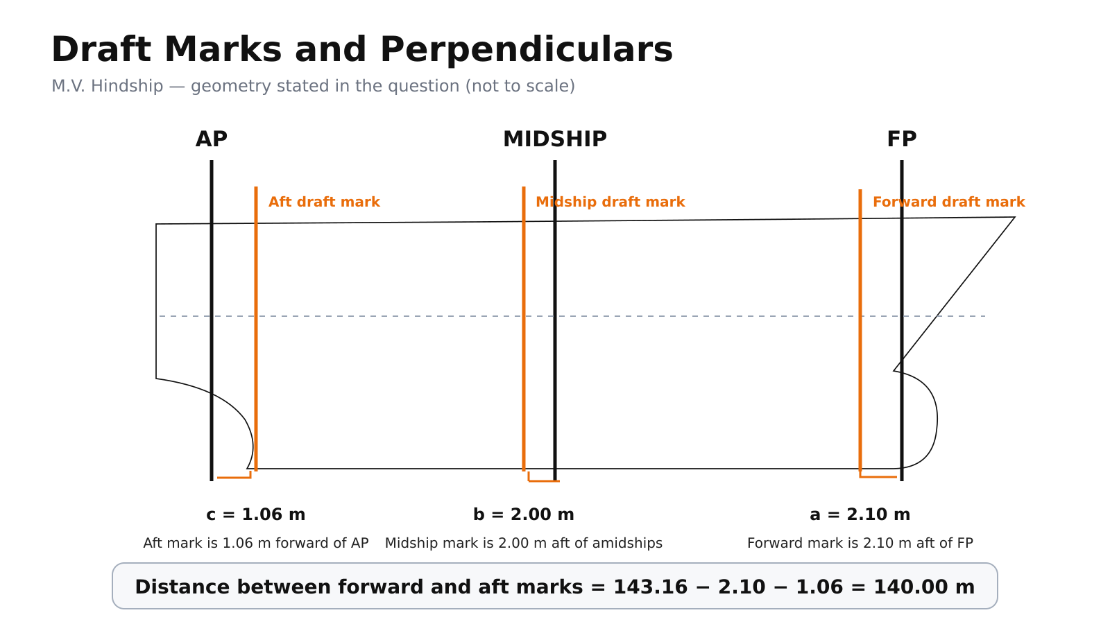
    Hindship draft marks showing the positions of the forward, midship and aft draft marks relative to FP, amidships and AP
    Example draft-mark geometry from a WayToMasters Hindship problem. The diagram is not to scale.

    2. Calculate the mean draft

    The simple mean draft is the average of the forward and aft drafts.

    Mean Draft = (F + A) ÷ 2

    This value does not by itself account for hull deflection indicated by the midship draft.

    3. Calculate the mean of mean of means

    When forward, aft and midship drafts are available, use:

    Mean of Mean of Means = (F + A + 6M) ÷ 8

    Worked example

    A ship has the following observed drafts:

    • Forward: Port 7.96 m, Starboard 8.00 m
    • Midship: Port 8.26 m, Starboard 8.40 m
    • Aft: Port 8.58 m, Starboard 8.64 m

    Step 1. Average each pair

    F = (7.96 + 8.00) ÷ 2 = 7.980 m

    M = (8.26 + 8.40) ÷ 2 = 8.330 m

    A = (8.58 + 8.64) ÷ 2 = 8.610 m

    Step 2. Calculate the simple mean draft

    Mean Draft = (7.980 + 8.610) ÷ 2 = 8.295 m

    Step 3. Calculate the mean of mean of means

    (7.980 + 8.610 + 6 × 8.330) ÷ 8

    Mean of Mean of Means = 8.32125 m

    Trim and hull deflection

    Observed Trim = A − F

    Observed Trim = 8.610 − 7.980 = 0.630 m by the stern

    • If the midship draft is greater than the simple mean draft, the vessel is sagging.
    • If the midship draft is smaller than the simple mean draft, the vessel is hogging.

    Mean draft is not always the hydrostatic draft

    Before entering the hydrostatic tables, check whether the observed marks must be corrected to FP, amidships and AP. A first trim correction may then be required to obtain the hydrostatic draft at the tabulated reference position.

    Do not enter the hydrostatic tables using an uncorrected draft unless the question permits it.

    Common examination mistakes

    • Using one side’s draft instead of averaging port and starboard.
    • Confusing mean draft with the mean of mean of means.
    • Ignoring the midship reading when hogging or sagging is present.
    • Reversing the sign of trim.
    • Using observed drafts without correcting them to the perpendiculars.
    • Entering hydrostatic tables before applying the required trim correction.
    • Rounding intermediate values too early.
    • Leaving units out of the working or final answer.

    Educational material for examination preparation. Always follow the applicable official syllabus, approved ship data and examination instructions.

    Chief Mate Hindship Course

    Continue with nine complete examination-style problems.

    • Written solutions
    • Video explanations
    • Formula-first working
    • 180 days of access

    ₹499 regular price

    ₹399 launch price

    One-time payment. Access is normally activated automatically after successful payment.